Geoida
Help
|
|
Geoida |
Least Squares Network Adjustment |
There are two ways in which a least squares network adjustment may be computed using options in the Survey menu:
The default least-squares adjustment mode in any of these options is 2D-horizontal; if there are complete vertical observations then a 1D-vertical adjustment will also be computed; 3D adjustment is only available from within the alternative Least Squares Network Adjustment option listed next.
Refer to the topics above for further details of the options using this setting for the least-squares adjustment of standard traverses.
| Note - Both of these methods use exactly the same adjustment routines and produce the same adjustment summary and log file. However the Least Squares Network Adjustment option provides a far more comprehensive range of options to use, it is the preferred option where manipulation of individual observations may be required, and it is the only one of the two options that provides for 3D terrestrial observations, GNSS data, and localisation/site-calibration. |
The following comments in this topic refer in particular to using
the Least Squares Network Adjustment option.
Select Least Squares Data Set
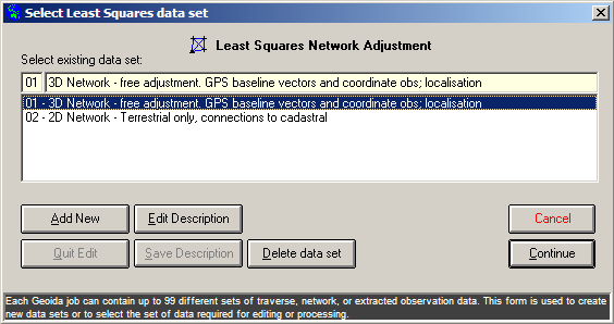
When the Least Squares Network Adjustment option is selected from the Survey menu the Select Least Squares Data Set window is displayed whereby a new set of least squares network data may be defined and described, or an existing set may be selected.
|
|
More Info: |
When Geoida is running, details of the purpose and use of each control in this window will be displayed in the bottom panel when the mouse is passed over any active object. |
If no data has been entered previously in this option for the
current job or if the Add New button is clicked, Enter
new data set description is shown above the empty
description field. Enter a suitable description for the least
squares data set for which observation data is about to be entered
and press Save Description to store. The description entered
will now be added and selected in the list below. To proceed to
enter the observation data, click Continue.
If data has been previously entered for the current job, a list of network data descriptions will be displayed - select any set required for editing or processing and click Continue.
Least Squares Network Adjustment
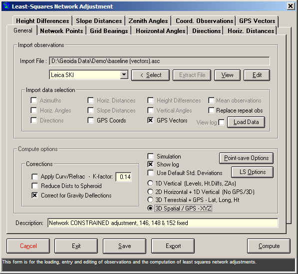
The Least-Squares Network Adjustment window is displayed when the Least Squares Network Adjustment option is selected.
|
|
More Info: |
When Geoida is running, details of the purpose and use of each control in this window will be displayed in the bottom panel when the mouse is passed over any active object. |
This option performs least squares network adjustments in the following 1D, 2D and 3D adjustment modes:
There are a number of tabs which divide the data entry window into three main categories:
General tab
Compute options
The lower section of this tab (the Compute options frame) controls the primary functionality for the Least Squares Network Adjustment option; located here are general settings and options that are defined prior to executing the adjustment process. Most of these options are covered in sufficient detail in the Instant Help panel at the bottom of the window, however further details are available regarding the following:
Data Import
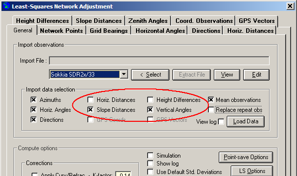
The upper section of this tab (the Import observations frame) is for importing existing observation data from file in any of the listed formats. If either the Geoida Standard Extract file or Geoida Manual Traverse set options is selected, the Extract File or Traverse Set button (depending on the option selected) will be enabled if the corresponding data has already been created from the prior processing of another Survey menu option within the current job. However an Extract file for a different job may be selected for import by clicking the <Select button.
Important details about the conventions used to distinguish different observation types recorded in an Extract file may be found at Observation Conventions and Types for Traverse and Network
Normal field observation data (SDR 2x/33, Civilcad Neutral, CDS Stadia etc) may be imported into the current data set as either 2D horizontal distances and height differences, or 3D slope distances and vertical (zenith) angles - this is determined by the checkbox settings in the Import data selection frame on the General tab; both 2D and 3D observations cannot be selected together.
|
Note that SDR 2x/33 observations read from MC ("Meaned and/or Corrected") records have already been corrected for instrument and environmental factors, so instrument and target heights of 0.000 will be assigned for slope distances and vertical angles.
A slope distance is assumed when BOTH the distance & a VA are present; if only a distance is present it is assumed to be horizontal. Note that 3D slope distance observations are not reduced further and are not balanced with reciprocal observations over the same lines.
When the data file has been selected, the Import data selection frame defines what observations are to be read from the file; de-select any types not required.
Cross the Replace repeats checkbox if observations have already been entered previously but observations between the same points are to be replaced with any that might occur within the imported observations (does not duplicate existing observations). Un-cross the box if the duplication of repeated observations is allowable (eg observations made over the same lines but in different circumstances or conditions, different instruments or operators, etc).
Click Load Data to import the new observations - a brief report will be displayed to summarise the types of observation loaded.
Data export - Any of the normal terrestrial (i.e.
non-GNSS) observation data types may be exported to a CSV Raw
Export file; observation tabs that are set inactive
(Observations active checkbox un-crossed) or individual
disabled observations, are omitted. Check for the required
observations and click the Export button at the bottom of
the form. Refer to Import and Export
Formats for more information about the CSV Raw
export format.
Network Points tab
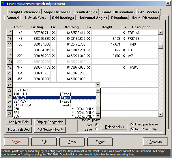
If observation data is imported via Load Data on the General tab, the required points are automatically loaded from imported data file (depending on the format type and inclusion of the points as control or observed points) or from the job database, and are entered into the Network Points tab. Points already defined as 'Fixed' will also be set Fixed here - note that the 'Fixed' setting for individual points in the imported data or, in their absence, in the main database, takes precedence over the 'Fixed' flag in the Enter Points options.
|
|
More Info: |
When Geoida is running, details of the purpose and use of each control in this window will be displayed in the bottom panel when the mouse is passed over any active object. |
Adding Points - Additional existing points may be loaded by clicking into the Point field and selecting the required point from the drop-down list of point numbers and descriptions.
Points recorded locally - Once existing points have been loaded into the form they become local to the form only - any modifications to the points are local only and are NOT saved back to the main database before computing an adjustment. This means that provisional or control point coordinate values may be changed to suit the needs of the adjustment without affecting the originally defined coordinates in the main database. New points may be added by clicking Add New - once again these new points are recorded locally only, but will be added to the main database if they are included in a computed network adjustment and the result of the adjustment is saved. New points added locally will appear in the drop-down list of points in the Point field with the tag '** LOCAL ONLY'.
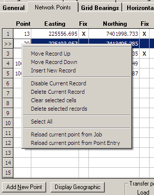
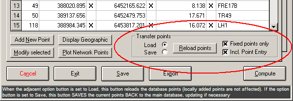
Re-loading and saving of network points - Points entered onto the Network Points tab are the observed and fixed control points comprising the network as required for adjustment. The points may have been placed there manually by selecting from points already defined in the main job database, or they may have been automatically selected from the database as observation data files were imported. However, as noted above, these points are only local to the Least Squares Network Adjustment option and may be changed from their original values. Thus to facilitate the easy transfer of these points between the Least Squares Network Adjustment option, the job database, and the Point Entry tables in the Points menu, both Load and Save operations are provided.
|
Figure 5: 'Network Points' tab - 'Transfer points' set for re-loading listed points from database and Point Entry tables |
|
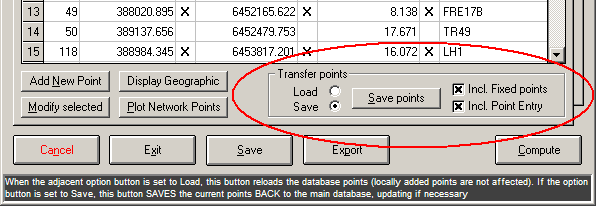
Figure 6: 'Network Points' tab - 'Transfer points' set for saving listed points to database and/or Point Entry tables |
|
Re-loading points - If it is desired to re-load the original coordinates of one or more of the listed points from the main job database, there are two methods available:
Saving points - Saving points from the Network Points tab back down to the main job database or into the Point Entry tables may be desired when the points have been defined locally only or when they have been edited, in order to update those recorded in the other locations. However note that the un-fixed points on the Network Points tab will generally be provisional values only - if the network is subsequently adjusted and the newly-adjusted points are saved according to the settings defined in the Point-Save Options on the General tab (see Processing), then existing point values in the job database or the Point Entry tables may be overwritten.
Editing points - It is not possible to edit details of any point directly on the form; however, if editing is required (for example to change a fixed point to un-fixed), double-click anywhere in the record for the required point, or select the record and click the Modify selected button, and the Modify Listed Point window will be displayed to allow editing.
Fix field - When a 'fixed' point is first loaded, all three Fix fields will be marked 'X' to indicate that all coordinate values are fully fixed and the point will be treated as a fixed control point. If it is desired to un-fix such a point or to hold only one or two of its coordinates 'fixed', it will first be necessary to modify the point (refer to Editing points above) and un-tick the Fixed checkbox which will then clear the three Fix flags when the point is saved. Individual coordinate values for a point may now be fixed or un-fixed as required - the three values are not inter-dependant. For example, the easting could be held fixed while allowing the northing and the height values to remain un-fixed and therefore subject to adjustment. In such a case, the point will be treated as an un-fixed point during adjustment and will be listed as such, but any of its constrained coordinate values will be flagged with '#' and accompanied by the note Single coordinate of un-fixed point held FIXED.
|
|||||
Network Points tab section - refer also Alternative
Coordinate Display ('Network Points' and 'Coord. Obs'
tabs)
Observation data tabs
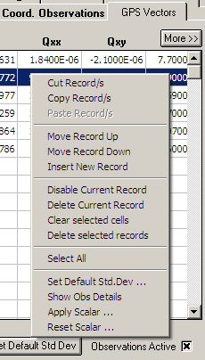
Observations may be imported from an existing data file as previously discussed, or may be manually entered. Observations can be entered in any order and in any combination, and may be freely edited. It is not necessary to manually enter standard deviation values for every record - simply set a default value in LS Options on the General tab, then click the Set Default Std Dev button to fill all standard deviation fields on the current tab with the default values defined.
Particular observations may be excluded from an adjustment by right-clicking into the record number field (left-most column) and selecting Disable Record. All observations of a particular type under one tab may be excluded from an adjustment by un-crossing the Observations Active checkbox on the current tab, however an error will result if there are insufficient active observations to permit the adjustment. Note that if the adjustment option is set to 1D Vertical on the General tab, this will automatically exclude all horizontal observations anyway.
An observation may be held 'fixed' (or constrained) by placing 'X' in the Fix field such as might be required when an angle of 180 degrees must be maintained for a point on-line between two others. This assigns a very small value to the standard deviation of the observation such that, even though it is still included in the adjustment, it is weighted so heavily that all adjustment is distributed to all other observations and the observation is 'constrained' to its original value with effectively no change of any significance being made to it.
Context Menu - observation data tabs
|
|||||
Slope Distances ignored in 2D adjustments
Slope distances are not reduced to horizontal for a 2D adjustment but are ignored, because valid height values for the corresponding points may either not exist or may be provisional values only, resulting in errors in the reduction to horizontal.
Horizontal Distances in 3D adjustments
Horizontal distances can be included for adjustment in 3D but are better suited to shorter distances only (not geodetic), since the length determined for any specific line may vary depending on which end of the line the observed slope distance is reduced to horizontal. It is doubtful if horizontal distances are ever “observed” as such since they will always have been reduced from measured slope distances.
IMPORTANT NOTE - Horizontal distances should NOT be used if they have been reduced from slope distance observations over the same lines that will ALSO be used in the adjustment.
Alternative Coordinate Display ('Network Points' and 'Coord. Obs' tabs)
Coordinates on the Network Points and Coord.
Observations tabs may be displayed in alternative systems (i.e.
Grid coordinates, Geographic or Cartesian XYZ/ECEF), depending on
the job Coordinate System as set in Job
Configuration, and the Coord. Obs Type setting on the
Coord. Observations tab.
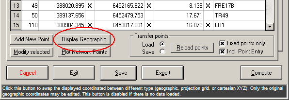
The different coordinate types are displayed by clicking the Display (coord-type) button which will show a different caption depending on which coordinate type is available next - simply cycle through the types available until the required type is displayed. On the Network Points tab the primary type initially displayed will always be as defined by Coordinate System in Job Configuration.
|
Figure 9: 'Network Points' tab - Points displayed as Grid coordinates; click 'Display Geographic' button to view as geographic coordinates (Figure 10) |
|
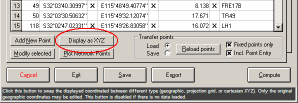
Figure 10: 'Network Points' tab - Points displayed as Geographic coordinates; click 'Display as XYZ' button to view as Cartesian XYZ coordinates (Figure 11) |
|
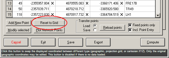
|
Figure 11: 'Network Points' tab - Points displayed as Cartesian XYZ coordinates; click 'Reset to Grid' button to view as Grid-Projection coordinates (Figure 9) |
On the Coord. Observations tab the points are at first
displayed according to the Coord. Obs Type setting where
GPS (ITRF/wgs84) will display Geographic coordinates, and
any other setting will display the coordinates as defined for the
job.
The following table summarises the situations where point coordinates may be displayed in alternative systems:
| Job Coordinate System | |||||
| Plane * | Grid Projection | Geographic | |||
| Current Tab |
'Coord obs type' setting | Comment | Alt. Coords Display | Alt. Coords Display | Alt. Coords Display |
| Network Points | n/a | Job Datum | No | Grid/Geog/XYZ | Geog/XYZ |
| Coord. Observations | GPS (ITRF/wgs84) | The coord and/or vector obs are on ITRF/WGS84 | n/a | Geog/XYZ | Geog/XYZ |
| Coord. Observations | Job Datum | The coord obs are on the Job Datum (Grid/Geog) | n/a | Grid/Geog/XYZ | Geog/XYZ |
| Coord. Observations | Non-geodetic | The coord obs are Grid coordinates | n/a | Grid only | (None) |
| Coord. Observations | Other | The coord obs (Grid) require localisation to the job datum - (Plane job only) | No | n/a | n/a |
Localisation of point coordinates or GPS vector observations
Normally localisation will be used for post-processed GPS baseline and point observations so that observations made on the GPS WGS84 or ITRF datum can be localised onto the job datum prior to least squares network adjustment. However localisation may also be necessary in other situations, such as to derive transformation parameters to transform points on a foreign datum (entered as points on the Coord Observations tab with the coordinate system defined by the Coord Obs. Type drop-down list) to the current job datum.
For further details regarding localisations refer to topic Localisation (Site Calibration) .
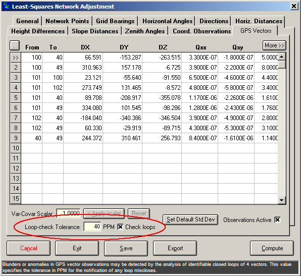
GPS Vector loop closures
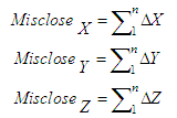
To test observed GPS baselines for blunders or large random errors, all loops of 3, 4 or 5 lines in the network will be detected and compared for misclose against the Loop-check Tolerance PPM on the GPS Vectors tab.
|
Ideally the algebraic sums of the delta-X, delta-Y and delta-Z components in a loop should equal zero. Loop misclosures in the X, Y and Z components are computed as
|
Details of any loops that exceed the specified tolerance will be displayed, at which point the user may choose to abandon the adjustment and return to peruse the data, or to continue.
Leica SKI format
Data Format - For the importation of Leica SKI observation data into the Least Squares Network Adjustment option, the correct options must first be set when exporting the file from Leica Geo Office as follows:
Failure to set these options correctly will result in the failure to import the point and vector observation data into the Least Squares Network Adjustment option.
Point Classes - Leica SKI point classes listed in increasing hierarchical order:
Point records of all classes will be imported, but depending on the option in use, some points may be updated by any subsequent records encountered where the same point has been assigned a higher class. Thus, in the case of the Import Points option, the record with the highest class will always be the one saved for the final point values.
In the case of importing observation data into the Least Squares Network Adjustment option, lower class coordinate observations will also be recorded even though a record with a higher class may be read later from the file. Thus observations of the same point may appear more than once in the Coord Observations tab but the record with the highest record number will always be of the highest available class. In this case it is up to the user to disable or remove point observation records of lower classes if not required.
Note - Points of the REF class are always given in the WGS84 coordinate system and thus may not be suitable for inclusion and should be omitted if other coordinates and/or baseline observations have been recorded in the local system.
Trimble Geomatics Data Exchange Format
For correct processing, point records in the [Keyed-In Coordinates] section of the data file should contain not only the horizontal coordinates but also BOTH geoidal/orthometric AND ellipsoidal heights from which the geoid N-value (undulation) is also computed. After data has been imported, the points in the Network Points tab should be checked for valid height and N-value.
Processing
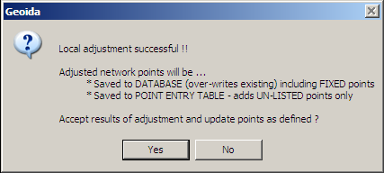
Click the Compute button to process the adjustment. Following the adjustment summary, a prompt similar to the following may be displayed:
|
If the adjustment is satisfactory, this message confirms the settings made for the Point-Save Options button on the General tab. A Yes response will write the adjusted coordinates to the main job database and/or Point Entry tables according to the settings shown. However if there are problems with the adjustment, errors are evident, or further refinement of the data, standard deviation values, etc is required, a No response will not save the adjusted points at this stage.
Refer to Network Adjustment - Least Squares for further details of the least-squares network adjustment and analysis process. For comparison with the prompt that follows adjustment by any of the Survey menu standard traverse processing options, refer also to the heading Accepting or rejecting results of adjustment within the same topic.
| Converted from CHM to HTML with chm2web Standard 2.85 (unicode) |