
Geoida
Help
|
|
Geoida |
Localisation (Site Calibration) |
Sections
|
Localisation (Site Calibration)
A 3D-similarity (Helmert) transformation may be computed from
GPS-derived point observations (ITRF/WGS84 datum) or other point coordinate measurements, entered into the
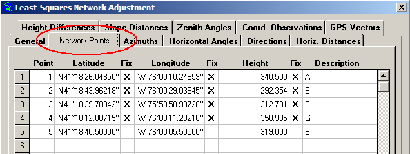
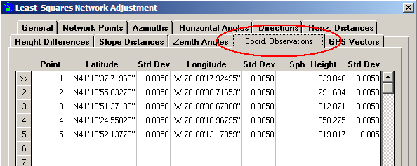
Coord Observations tab and matching fixed control points on the
local job datum and defined on the Network Points tab. Based
on the computed transformation parameters, the remaining points and (optionally)
GPS baseline observations can then be localised onto the job datum
prior to least-squares adjustment of the network.
The computed transformation parameters are saved for re-use within the data set, and can also be saved to the Transformations library for use in any other job as a normal 7-parameter 3D Similarity transformation.
Normally localisation will be used for post-processed GPS
baseline and point observations so that observations made on the
GPS WGS84 or ITRF datum can be localised onto the job datum prior
to least squares network adjustment. However localisation can also
be used for other situations, most likely to derive transformation
parameters to transform points on a foreign datum (entered as
points on the Coord Observations tab with the coordinate
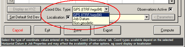
system defined by the Coord Obs. Type drop-down list) to the
current job datum.
|
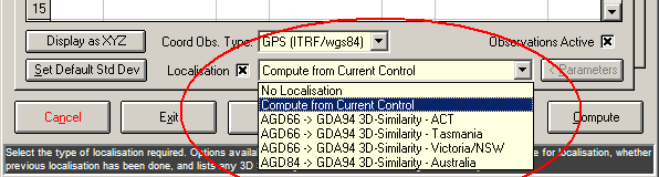
In such a case as this, the parameters may be computed (select Compute from Current Control in the drop-down list) from:
|
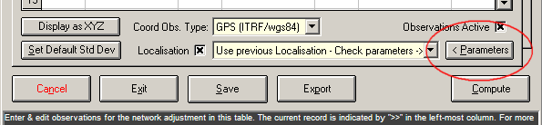
For NO localisation of current coordinate observations or vectors,
the observations must be set 'Active' but with
'Localisation' un-ticked; if observations are NOT active or
there are no coord observations, a localisation of GPS baseline
observations may still be performed by selecting 'Use previous
localisation - Check parameters' which will use the parameters
already used previously (this option listed only when a
localisation has already been computed), or an existing named
transformation may be selected from the list. Click the '<
Parameters' button to check the parameters of a previously-used
or previously-computed localisation or any selected pre-defined
transformation.
Localisation based on simple coordinate observations can also be done for standard survey jobs without any additional GPS-derived coordinate or baseline observations, or for those jobs configured for simple plane (non-ellipsoidal) coordinates. In such jobs coordinate "observations" may simply be points from another datum, however, all points on both the Network Points and Coord. Observations tabs must have valid heights; if the points have been defined with only 2D horizontal coordinates and no Height values, specify all the point heights as zero (0.000, not blank). With the Least Squares adjustment mode set to '2D Horizontal' and with 'Localisation' set to ‘Compute from Current Control’, on Compute the mode is temporarily forced into 3D-Terrestrial mode for the purpose of computing the 7 parameters for the localisation. In this case the parameters computed will effectively be 2D transformation parameters simply because there will be no vertical translation (tZ = 0.000) and no rotations about the horizontal axes (Rot-X = 0 and Rot-Y = 0). In 2D mode, set 'Coordinate Type' to 'Non-Geodetic' for Grid Projection jobs, or set to 'Job Datum' for Plane jobs. Localisation and adjustment with only point observations does not require any other observation data type to be present or active.
If it is only desired to compute the localisation or
transformation parameters or to localise/transform a group of
points onto the job datum, it is NOT necessary to continue with a
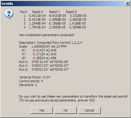
network adjustment. When a new localisation is computed, the
residuals from the adjustment of the selected matching and fixed
points are displayed for verification - the user may stop further
processing and return to the option at this point. See Figure 6 - Localisation parameter
report.
To localise or not?
GPS baselines measured on the WGS84 or ITRF datum should be
localised or transformed to the local job datum by selecting
Localisation and setting the appropriate options on the
Coord Observations tab. However, even if localisation is
not requested, the least squares adjustment will still
adjust the observations into the required positions on the local
datum (i.e. scale, rotation, translation) except that the residuals
for the baseline components may appear larger than they should be
and mislead the user to a wrong conclusion about their
reliability.
If the local datum coincides well with the WGS84 datum in origin
and rotation, then the scale and rotation differences between the
two will be statistically close to zero and the need for
localisation of the GPS observations onto the local datum may be
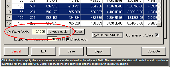
optional. It may be acceptable to simply scale individual baseline
observation variances/co-variances to improve the fit of the GPS
vectors to the local network control points - this may be necessary
simply due to residual errors or strain in the adjustment of the
original control within a broader network of control stations
enclosing the current area. If simple scaling is required, use the
Var-Covar Scalar on the GPS Vectors tab to scale
selected observations.
|
The observation variance-covariance values can be reset to their
original values by clicking the Reset button which inverts
the accumulated scalars on the selected observations.
However if the two datums or ellipsoids are not closely
coincident then it may be necessary to perform localisation before
adjustment to transform the GPS vector observations to realign them
within the local coordinate space. For example: "The GPS
measurements which are the usual output of the GPS post processing
software are based on the WGS84 ellipsoid and the S-JTSK local
datum is based on the Bessel ellipsoid. Thus, the reduction of
measurements to the S-JTSK mapping plane cannot be started from the
measurements resulting from GPS post processing software because
GPS and S-JTSK don't have the same ellipsoid."
['Derivation of some geometric parameters of GPS
measurements' - Adel Alfrehat, Janka Sabov and Marcel
Mojzes, 'Acta Montanistica Slovaca', Volume 10 (2005), No. 3, 310 -
316]
See Derivation of
Transformation Parameters for Localisation for further
details of localisation.
Availability of the Localisation Function
The following table summarises the situations in which localisation can be used as defined by settings on the Coord. Observations tab of the Least Squares Network Adjustment option and according to the current job's Coordinate System and Coord. Obs Type setting.
| Job Coordinate System | ||||
| 'Plane' | 'Grid Projection' | 'Geographic' | ||
| 'Coord obs type' setting | Comment | Localisation available | Localisation available | Localisation available |
| GPS (ITRF/wgs84) | The coord and/or vector obs are ITRF/WGS84 so MUST localise | n/a | Yes | Yes |
| Job Datum | The coord obs are on the Job Datum - localisation not required | n/a | No | No |
| Non-geodetic | The coord obs require localisation to the job datum (Grid job only) | n/a | Yes | n/a |
| Other | The coord obs require localisation to the job datum (Plane job only) | Yes | n/a | n/a |
The four observation types available on the Coord. Observations tab are as follows:
However, only two or three of these may be listed together
depending on other settings . Note that Non-Geodetic is not
available when set to GPS (ITRF/wgs84) mode, and GPS
(ITRF/wgs84) mode is not available when set to
Non-Geodetic. The reason for this is that
Non-Geodetic (i.e. Plane grid) mode is not relevant when
coordinate observations are GPS-derived and vice-versa. To change
the setting from Non-Geodetic (Plane grid) to display points
as GPS Lat/Long or XYZ coordinates, then first change the Coord.
Obs Type setting to Job Datum mode, then re-display the
current Grid coordinates as Geographic (Latitude/Longitude) or
Cartesian XYZ when the Display (coord.type) button is
enabled. Likewise, apply this procedure in a similar manner to save
GPS Geographic or Cartesian XYZ coordinates as Non-Geodetic
Grid. Note that the three types GPS (ITRF/wgs84), Job
Datum and Non-Geodetic are only listed together when the
coordinates are displayed as Grid in Job Datum mode.
Derivation of Transformation Parameters for Localisation
If the local ellipsoid is GRS80 and/or the local datum is consistent with the GPS system, then there may be little need to transform between WGS84 and GRS80, but if the ellipsoid for the defined job datum is different from GRS80 or WGS84 then a localisation may be advisable and indeed necessary. Knowledge of the local ellipsoid is really not necessary when localising from WGS84 as the transformation parameters are simply computed on the basis of whatever control points are available to be used; thus localisation can be performed in a Plane job with simple 2D or 3D cartesian (orthogonal) coordinates.
Localisation will be required ...
At least 3 matching pairs of points are required, with the observed positions entered in Coord. Observations, either as observed GPS points or points coordinated in another system or datum, and their matching known positions in the target job datum are set fixed in Network Points. A minimum of four pairs of points must be available as both observed and fixed positions for redundancy and to provide non-zero residuals. The selected control points should be distributed evenly across the project area to derive a better and more representative set of rotation and scale parameters for the overall network.
Note:
|
|
For representative transformation values for rotation and scale,
the control points selected should not be nearly co-linear and
should form a well-balanced and evenly-distributed triangular
network covering much of the area of interest. Excessive residuals
may be a result of insufficient spatial separation between control
points.
If a localisation is required and the Localisation option
is set to Compute from Current Control, the parameters will
be computed and applied to the observations prior to the network
adjustment. Details of the new parameters will be displayed for
confirmation for use in transforming the observed points and/or
vectors as follows:
|
After computing new localisation parameters and displaying a report as in Figure 6 - Localisation parameter report above, if Yes is clicked to continue the transformation as in item 1, the computed parameters are displayed again with the following prompt to save the details permanently to the Definitions library:
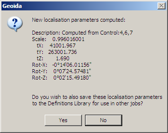 |
If the response is Yes then the details may be saved to Transformations in the Definitions Library as a 3D-Similarity transformation for re-use in other jobs. An opportunity is provided to edit the description to be added to the transformation as saved in the library:
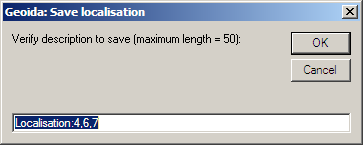 |
To save the localisation details, the default description offered may be edited to a preferred description, or accepted as-is and modified later in the Transformations option if necessary - click OK to save and continue the computations. Click Cancel to skip saving the details and continue.
Defining datums for saved localisations: A saved localisation becomes a 3D Similarity Transformation in the Definitions library. At the point of saving, the From Datum will be 'undefined', hence the datum names OTHER and LOCAL may be used respectively depending on whether the job is defined with an existing ellipsoidal datum or is Plane, and the To Datum will be the current job datum. The new definition should be edited in Transformations and valid settings for the From and To datums selected; the user may also change the Description but it will not otherwise be changed by selecting the datums as for normal transformations, and should be kept distinctive.
Existing transformation parameters - Existing
transformation or localisation parameters may be used to localise
coordinate or GPS vector observations - the parameters used do not
have to be derived from current data, and coordinate observations
on the Coord. Observations tab do not have to be entered or
enabled. However it is necessary for the Coord.
Observations tab to be set Active even thought there
might be no coordinate observations.
Two types of previously-defined parameter sets may be used:
Click the Parameters button to view details of the
localisation/transformation selected.
|
Observed Coordinates - In some cases, observed coordinates exported from proprietary post-processing GPS software may be unadjusted positions. Unless their standard deviations are relaxed, it is probably inappropriate to include these observations in an adjustment since they may distort the adjustment and the statistical results for the network. Similarly, unless observed coordinates are adjusted values, using them to compute localisation parameters is not recommended. Refer to Leica SKI point classes for more information. To remove observations from the network, either disable individual observations, or un-tick the Active checkbox for the whole observation type, but note that a localisation cannot be computed if the Observed Coords. type is set in-active.
| Converted from CHM to HTML with chm2web Standard 2.85 (unicode) |