
Geoida
Help
|
|
Geoida |
|
A parametric mathematical model is used to achieve the least squares adjustment algorithm for the variation of point coordinates. 1D vertical, 2D horizontal, and 3D adjustments may be made. Horizontal data can consist of normal traverses, or any combination of triangulation, trilateration, intersection or resection observations. If traverse/network data contains both horizontal and vertical elements, the horizontal point positions will be adjusted in 2D form and Geoida will then prompt for the adjustment of the verticals if required. 3D networks may consist of 1D, 2D and 3D conventional terrestrial observations plus GNSS observations - refer to 3D Adjustments for more information.
There are two main methods of performing a least squares network adjustment:
1. Set the Adjustment option to LS-Network in any of the Survey menu standard traverse processing options
2. Select the Survey menu Least Squares Network Adjustment option
Apart from these different means by which a least squares adjustment can be initiated, the computations and network summary report are otherwise identical, and except for additional provisions within the Least Squares Network Adjustment menu option, the following comments apply equally to any of these methods with minor variations only in regard to the editing of observation data.
Sections
|
Provisional coordinates
Provisional coordinates must be specified for all unfixed points - this may be accomplished either by entering the approximate point coordinates in the Enter Points option, or by pre-calculation of the data by another means, eg by the same option as would be used for the Least-squares network adjustment but specifying the None or Bowditch adjustment modes where a check may be made upon closure details for detection of any gross errors. But perhaps the most convenient means of creating new as-yet unadjusted points is to 'point-and-click' their approximate positions on-screen using Digitise Provisional Points - provided that the points retain their correct positional relationships to one-another and the provisional point tolerance (see next) is not set too small, the least-squares adjustment should converge and adjust them into their correct positions.
Levelling networks
Networks of height difference observations, derived by differential levelling or trigonometric heighting techniques, may be subjected to a least squares 1D adjustment. Surveys of pure levelling networks, i.e. with no horizontal observations, may be adjusted.
If point heights have not been computed by some other option, new unfixed points with provisional heights must be first created by entering their details in the Point Entry option - both fixed and provisional level points can be specified by point number and height only, leaving the Easting and Northing fields blank, in which case the value of 0.000 will be assigned to the Easting and Northing for such points. The observations are entered either in the Traverse option with the height differences entered into the VC fields (note - provisional levels cannot be specified in the ToRL fields), or in the Least Squares Network Adjustment option under the Height Differences tab.
There are two methods of weighting the observations ...
If the number of setups or levelling bays is known, the number is specified in the Extract file (refer to Extract file for format details) or the Bays field (Least Squares Network Adjustment option), and the weight is calculated as

|
If the number of setups or bays is not known but the distance is known, or if using vertical measurements derived by some means other than spirit levelling (eg by trig. heighting), the Distance field may be entered with the observation length whence the weight is calculated according to

|
If the Distance field is left blank, the distance is computed from the points' horizontal coordinates if available. For this reason, although it is possible to specify points in the Enter Points option having only heights and no horizontal coordinates, it is preferable to enter these if known, even if they are only approximate, so that appropriate weights may be computed related to the length of the observations. If no entered or computed distance is available, an observation's weight will be simply the inverse of the square of the standard deviation.
When computing a vertical adjustment in the Traverse or Process Extracted Observations options with the Use Default Std Dev check box crossed, the default standard deviation used for the vertical observations is the value specified for VC / Height Diff and the weight computed is based on the observation distance.
Note that in the adjustment report produced, the Sum of the adjustment amounts is meaningful ONLY in the case of a simple traverse or a single levelling run - in such a case the sum of the adjustments is simply the amount of the height misclose.
Weights
Weights are computed from the Standard Deviation values specified and are apportioned directly to both angle/direction observations and distance observations according to the length of observed lines such that an observation over a long line will have a greater weight than another over a short line. It is assumed that most distance observations made in current and future times will normally be made by electronic means whereas it has formally been the practise in the past to weight (manual) distance observations according to the inverse of the length of line.
If unit weights are required throughout, cross the Apply unit weights (all obs) check box in the Least-Squares Options window which is opened by clicking the LS Options button for the particular option selected; if processing an Extract file (Process Extracted Observations option), also cross the Use Default Std Dev check box adjacent to the LS Options button.
Standard deviations
When using the e-Data or Traverse options, the standard deviations specified are applied globally to all observations, depending on the observation type (i.e. angle, distance, etc).
However, if it is necessary to apply different standard deviations to individual observations to account for different precisions, variations in observing conditions, or to constrain certain observations, the Extract file produced by a different processing option may be used since the standard deviation values for individual observations may be edited before re-processing with the Process Extracted Observations option. Refer to Extract file for further details.
(Note : The Process Extracted Observations option permits either the global application of default standard deviations for all observations, or the use of the individual values specified within the Extract file, by crossing or uncrossing the Use Default Std Dev check box as required.)
Constraints
Constraints may be applied to particular observations within a network to hold them 'fixed' by setting the standard deviations to a very small value. Such observations will thus be weighted so heavily that adjustment will be distributed throughout the remaining normally-weighted observations so that the heavily-weighted observations remain effectively unadjusted.
1. To apply constraints for the Process Extracted Observations option by editing an Extract file, change the standard deviation values for the observations to be held, to a suitable single low value. When more than one observation of a certain type is to be constrained, be careful to set each of their standard deviations to the same value.
Note : the standard deviation of an observation to be constrained should not be set to zero - if it is, Geoida will change it to a preset small value (0.001 second or 0.01 metres, according to the observation type) and advise the user of the change. The smallest positive value that can be entered into the appropriate field will also constitute an acceptable value.
2. For the Least Squares Network Adjustment option, there are two ways in which constraints are applied:
Note: Geoida does not perform a constraint-free adjustment. To test the internal consistency of a network of observations, perform a 'minimum constraints' adjustment where all datum defects will be removed, i.e. there must be no rank defect or the adjustment cannot be run.
See Minimally-constrained network below for further details.
Network Rank and Datum Defects
A network containing a datum defect (insufficient datum definition or rank defect) cannot be adjusted. The table below shows the datum parameters required, and the constraints necessary to correct rank defects, for various types of networks.
| Position | Rotation | |||||||||||
| Type of Network | Observation type | X | Y | Z | X | Y | Z | Scale | Datum Parameters Required | Defined by Obs | Datum Defects | Minimum Constraints to Fix |
| 1D Level Network | Height Diff | - | - | x | - | - | - | y | 2 | 1 | 1 | 1 Height |
| 2D Trilateration | Horiz. Dist | x | x | - | - | - | x | y | 4 | 1 | 3 | 1 (X,Y) plus 1 X or 1 Y |
| 2D Triangulation | Azimuth | x | x | - | - | - | y | x | 4 | 1 | 3 | 2 (X,Y) or 1 (X,Y) + 1 X, Y or Dis |
| 2D Triangulation | Horiz. Angle / Direction | x | x | - | - | - | x | x | 4 | 0 | 4 | 2 (X,Y) or 1 (X,Y) + 1 Az + 1 X, Y or Dis |
| 3D Terrestrial | Spatial Distance | x | x | x | x | x | x | y | 7 | 1 | 6 | 2 (X,Y,Z) or 1 (X,Y,Z) + ZA, Az etc |
| 3D Terrestrial | Zenith Angle | x | x | x | y | y | x | x | 7 | 2 | 5 | 1 (X,Y,Z) + ZA, Az Sp.Dist etc |
| 3D GPS | GPS Vector | x | x | x | y | y | y | y | 7 | 4 | 3 | 1 (X,Y,Z) |
| 3D GPS | GPS Coordinate | y | y | y | y | y | y | y | 7 | 7 | 0 | None |
| where: | Height | = | Fixed height |
| (X,Y) | = | Point fixed horizontally in X & Y | |
| (X,Y,Z) | = | Point fixed horizontally in X & Y and vertically in Z (or Height) | |
| X | = | Fixed X coordinate component | |
| Y | = | Fixed Y coordinate component | |
| Z | = | Fixed Z (or Height) coordinate component | |
| Az | = | Fixed azimuth | |
| Dis | = | Fixed horizontal distance | |
| Sp.Dist | = | Fixed spatial/slope distance | |
| ZA | = | Fixed zenith/vertical angle |
Assessing results of adjustment
The statistical analysis follows the recommendations of the Australian Inter-governmental Advisory Committee on Surveying and Mapping (ICSM) Geodesy Group as detailed in the 'SP1' document Standards and Practices for Control Surveys (SP1) Version 1.3, a publication produced in 1986 as a revision of Special Publication 1 (SP1) Standard Specifications and Recommended Practices for Horizontal and Vertical Control Surveys which was first published by the National Mapping Council of Australia in 1966. For full details of testing procedures, specifications and standards, refer to the SP1 document and other references (eg Geodetic Network Analysis and Optimal Design - Concepts and Applications - Kuang)
Following the least squares adjustment of a network, the a-posteriori statistics are analysed by the application of various tests, at selectable confidence levels as defined in Least-Squares Options, to identify any observation outliers and to examine the sample variance factor. If this analysis is satisfactory, the relative error ellipses are used to determine the class of survey achieved. For a reliable test of the relative error ellipses in accordance with SP1, the observation a-priori standard deviations should be modified by trial and error and adjustments repeated until the variance factor is as close to 1 as is reasonably possible to achieve.
The major stages in the network adjustment and analysis of results are as covered in these sections that follow:
It might also be found useful to refer to Least Squares Adjustment - Tips and Suggestions in Frequently Asked Questions.
Minimally-constrained network
For statistical testing of the internal consistency of the network, there should be a minimum number of fixed points assigned. This would normally be achieved by assigning one fixed point and a fixed bearing or two fixed points for position and orientation in a 2D network, or one fixed point for a 1D levelling or trig. heighting network. A simple traverse with no internal bracing would be a special case that may require assignment of a small number of additional fixed points to adequately define and orientate the 'network'.
When adjustment and testing of the minimally-constrained network has been completed, additional fixed points may then be assigned in order to connect the network to surrounding control. It is inappropriate to test a fully constrained network because of the strain that may be placed upon the observations due to inconsistencies or errors within the surrounding control which would then adversely affect the precision reported for the local survey. Testing a minimally constrained network will at least verify the internal consistency and precision of a local survey even if it does not relate so well to surrounding control.
Convergence of Adjustment
Iteration continues until a pre-set maximum number of iterations
is reached or until convergence or divergence is determined by one
of two methods.
NOTE - With a 3D adjustment (particularly) it is possible that the reference variance of the overall adjustment may be smaller before convergence than after (because convergence is tested in BOTH horizontal and vertical planes) and the convergence criteria may be satisfied at the same time as the adjustment begins to diverge or shortly thereafter. Thus a slight increase in the variance (less than 1%) is permitted for another iteration.
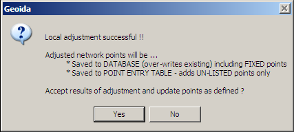
Accepting or rejecting results of adjustment
At the conclusion of the adjustment and prior to returning to the observations data, Geoida will prompt in one of two ways, depending on which of the two main methods of performing a least squares network adjustment was used:
.PNG)
|
|
If the adjustment is satisfactory, this message confirms the settings made for the Point-save Option on the General tab. A Yes response will write the adjusted coordinates to the main job database and/or Point Entry tables according to the settings shown. However if there are problems with the adjustment, errors are evident, or further refinement of the data, standard deviation values, etc is required, a No response will not save the adjusted points at this stage.
Note that a Yes response in both of these methods cannot be undone except by closing the job without saving or by Undo Changes (which will also discard all changes to the job since it was last saved).
| Converted from CHM to HTML with chm2web Standard 2.85 (unicode) |