
Geoida
Help
|
|
Geoida |
Projection |
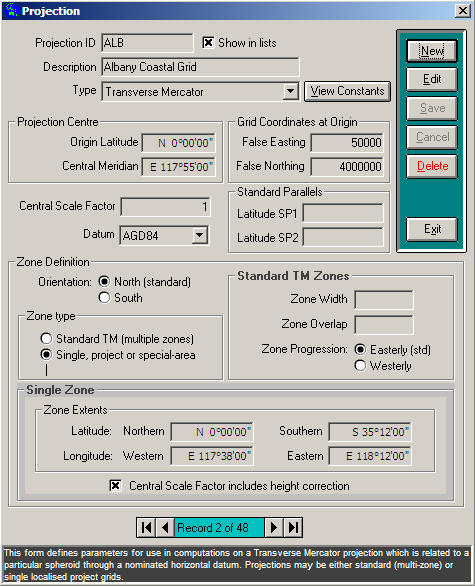
This option defines parameters for a range of commonly-used grid projections and associates them with a particular spheroid through the nominated horizontal datum. The Projection window is displayed when this option is selected.
|
|
More Info: |
When Geoida is running, details of the purpose and use of each control in this window will be displayed in the bottom panel when the mouse is passed over any active object. |
A projection defined in Geoida may be one of the following types:
To add a new projection, click the New button and select the type required in the Type drop-down list; various of the displayed fields and controls may be activated, disabled or re-named depending on the type selected. A Transverse Mercator projection may be defined to comprise a number of sideways-overlapping zones (Standard TM (multiple zones) setting), or a single zone (Single, project or special-area setting); all other projection types occupy single zones only and are always set to Single, project or special-area.
Projection Constants - When a projection has been defined and saved, the View Constants button will be enabled to display a number of constant values and other information about the projection as defined; this will permit the user to confirm that the projection has been defined correctly by comparing with published data.
Since a large number of projections may be defined, by crossing the Display in lists checkbox, only those projections that are of interest for typical projects will be displayed in the list of projections available in Job Configuration. This feature will eliminate unwanted projections that would otherwise clutter the list with projection names that may never be used.
Sections
|
Transverse Mercator
|
Transverse Mercator
The Transverse Mercator projection algorithms used in Geoida are largely derived from The Australian Geodetic Datum - Technical Manual, v2.2. See References for more details of consulted works.
Standard Grids
A standard Transverse Mercator grid projection is defined by the Standard Grid setting - a standard grid is usually one defined by a number of zones of regular width extending longitudinally around the globe. The Universal Transverse Mercator (UTM) consists of 60 zones (numbered 1 to 60) of 6 degrees of longitude width and 30 minutes sideways overlap, extending between 84 degrees north latitude and 80 degrees south latitude.
Zone Numbering - To correctly identify a zone in a
multiple-zone projection in Geoida, the zone's reference number
must be the actual sequential number of the zone as counted from
the primary zone, as is the case for the UTM. However for cases
where zones are 'named' according to a scheme in which the zone
name is not the zone's numerical sequential number for the
particular projection, it may be necessary to determine a zone
reference number from which the correct longitudinal position
around the Earth can be determined for coordinate conversions and
other ellipsoidal computations. Thus the zone sequence
number is used which may not necessarily be the same as the
common name by which a zone might be referred.
For example, the South African Gauss Conformal projection has zones 2 degrees in width but which are named according to the central meridian degree value such as "Lo19", where the Central Meridian is 19 degrees, but it is actually the 10th zone in the series. To convert the name "Zone Lo19" to the correct sequential zone number:
Zone sequence number = (Lo-zone + 1) / 2, i.e. (19 + 1)/2 = 10
Hence "Lo19" is actually Zone 10 in the sequence. Conversely, to determine the zone name from the sequence number:
'Lo' Zone = (True Zone x 2) - 1, i.e. (10 x 2) - 1 = 19, hence "Lo19"
Recommendation:
An alternative treatment would be to set up each zone as a
Single-zone projection. Any point conversions required
between a job's default zone and an adjacent zone could be
accomplished by a Zone-to-Zone transformation.
Single-zone/Special-area Project Grids
A 'Single-zone/Special-area Project Grid' projection is a special case Transverse Mercator projection defined for a limited area but which still enables the same mathematical formulae to be used as for any standard TM projection to compute accurate Transverse Mercator grid projection coordinates.
A Special-area Project Grid will usually be defined for an area where there will be long-term mining, engineering or other development projects which will require the frequent conversion of coordinate values into standard wide-scale coordinate and information systems. The primary benefit of a Special-area Project Grid is that coordination of positions and inverse measurements can be derived using simple plane geometry techniques such that acceptable levels of error will not be exceeded provided that the limits of the grid extents are not compromised. If required, coordinate values may also be readily converted between the project grid and standard TM or geographic values.
However, in Geoida the usual Transverse Mercator algorithms involving scale factor and arc-to-chord correction are used for direct and inverse computations on a project-grid system, hence accuracy is maintained. So for cases where a greater degree of accuracy and confidence in results is required, such as in the establishment and adjustment of control or the extraction of inverse details between coordinated points, Geoida's range of options applying standard Transverse Mercator formulae provide the user with a means of thus preserving accuracy by computing correct geodetic values.
Transverse Mercator 'project grids' were introduced in Western Australia to simplify the calculation of positions and dimensions for engineering-type construction and development projects so that plane geometry computations could be used to both coordinate position and extract dimension data within acceptable precision limits. Because the project grids are based on the Australian geodetic datum, a common frame of reference for conversion between project-grid coordinates and the national geodetic network is provided through the Transverse Mercator system.
Details of Project Grids for Western Australia which are not already defined in the Geoida library may be obtained from Geodetic Services, Landgate.
NOTE - Special-area Project Grid projections may incorporate a correction for terrain height into the value for Central Scale Factor so that measured or set-out distances may be derived directly from the point coordinates by simple plane geometry if desired. In these cases when processing observations using options in the Survey menu, the height correction should always be applied to measured ground distances to compute correct Transverse Mercator coordinates, i.e. tick the Reduce distances to spheroid checkbox where it appears in any option.
For further details concerning Special-area or Project Grid projections refer to the Spheroidal distance height correction section in the Corrections Applied topic.
Lambert's Conformal Conic Projection
Lambert conformal conic projections may be defined as either one or two standard-parallel variants. There is very little difference between the formulae for either; each is defined with a unit scale factor (1.000) along the single parallel (tangent projection) or along both standard parallels (secant projection) as the case may be.
The Lambert conformal conic projection algorithms used in Geoida are derived primarily from the OGP Publication 373-7-2 Coordinate conversions and transformations including formulas where the derivation of formulae is based on Map Projections - A Working Manual by Snyder, but with modifications for global application. No simplifications or approximations are applied.
Algorithms for arc-to-chord correction and line-scale factor are based on rigorous formulae in NOAA Manual NOS NGS 5, 'State Plane Coordinate System of 1983' - James Stem (March 1990).
See also References for more details of consulted works.
Mercator
Mercator projections are available as three variants with the following features:
The definition of Variants B and C is very similar and either may be used for the same result.
The Mercator projection algorithms used in Geoida are derived from OGP Publication 373-7-2 Coordinate conversions and transformations including formulas without simplification. Where computations require a value for line-scale factor, the simplified standard algorithm (k1 + 4km + k2)/6 is used, noting that scale increases in an extreme non-linear fashion with increase in latitude, hence scale becomes unreliable except in a band close to the equator. See also References for more details of consulted works.
Oblique Mercator
The Oblique Mercator projections are available as three 'Hotine' variants where variants 'A' and 'B' differ only as much as where the false grid coordinates are applied (Variant 'A': natural origin; Variant 'B': projection centre). The algorithms used in Geoida for these variants are based on the OGP Publication 373-7-2 Coordinate conversions and transformations including formulas where the formulae are derived from Snyder's Alternate 'B' variant, with modifications for global application. No simplifications or approximations are applied.
The 'SPCS 1-Pt' variant (for use in the USA) produces the same results as the Hotine Variant 'A' but uses a different set of formulae as defined by NOAA Manual NOS NGS 5 State Plane Coordinate System of 1983 by James Stem, where the central line is defined by azimuth through a single point, the natural origin - the 2-point central line variant is not provided.
If the Skew angle of the central line is not stated for a particular projection it may be assumed to be the same as the line Azimuth.
In computations where grid convergence, arc-to-chord correction, and line-scale factor are required, the source for algorithms is the rigorous formulae in NOAA Manual NOS NGS 5 State Plane Coordinate System of 1983 by James Stem.
See also References for more details of consulted works.
Plane Projection
A 'plane' projection is a special-case projection that should not be defined as a projection by this option but may be set in Job Configuration for occasions when it may desirable to compute plane coordinates by simple geometry only, in which case no geodetic algorithms are applied.
| Converted from CHM to HTML with chm2web Standard 2.85 (unicode) |